Schlagwort-Archive: C64

C64 Ersatz-Ein-/Ausschalter

Im Forum hat Gerrit als Lösung mit einen 0,25€ Schalter von Pollin vorgestellt (Link)

Nachdem die Ersatzschalter bei Retro-Donald ausverkauft sind und anscheinend auch nicht wieder reinkommen habe ich mich mal umgesehen was als Ersatz benutzbar wäre. Muss ja nicht perfekt sein sondern von aussen stilecht aussehen und funktionieren.

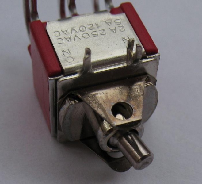
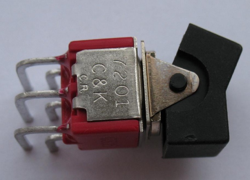
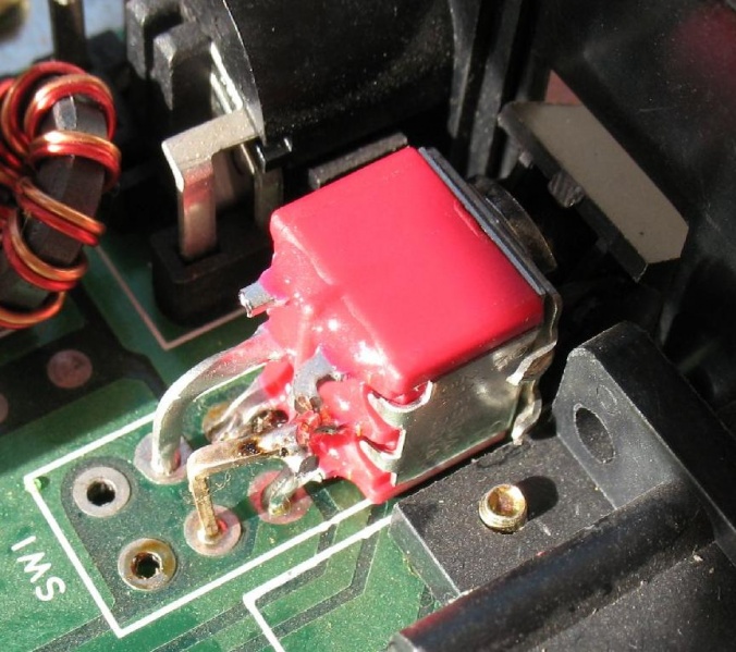
Letzte Woche habe ich bei Pollin die Nummer 420 632 für einen unschlagbaren Preis (25 Cent!) gefunden und gleich ein paar bestellt. Sieht auf dem Bild nicht besonders passend aus, aber wie man auf den angehängten Bildern sieht ist die Wippe nur aufgeklipst, die gleiche Art der Befestigung der Wippe wie bei den Originalschaltern des C64, mit einem sehr kleinen Schraubenzieher hatte ich kein Problem sie zu entfernen (siehe Bild 2) und die Wippe eines defekten C64-Schalter aufzuklipsen. Das löst schonmal das erste Problem und man könnte ihn direkt in einem C16 oder Plus/4 verwenden. Für die Verwendung in einem C64 ist etwas Bearbeitung der Anschlüsse nötig wie man auf dem dritten Bild sieht. Hierbei mit Gefühl arbeiten und sich etwas Zeit lassen. Drei davon kann man direkt passend biegen, der vierte braucht eine Verlängerung, ich habe mir einen Draht des defekten Schalters geliehen. Die zwei übrigen Anschlüsse werden im C64 nicht verwendet, also habe ich sie einfach entfernt. Ergebnis: C64 funktioniert wieder und ein sattes Schaltgefühl.

Natürlich ist das ein Hack, aber ich finde besser so als kein Schalter… .Müsste genauso mit den Schaltern einer 1541-II, eines C128 und einer 1581 funktionieren.

Schalter:

Wippenhalterung:

Der eingebaute Schalter:

C64 Diagnose: The Commodore Diagnostician by Ian Perry

The Project 64 etext for Commodore diagnostics, converted by The
Basic Bombardier. This etext was created by concatenating several
documents into one. Please see the header of the particular document
for original sources.

The Commodore Diagnostician, by Ian Perry.
Ray’s C-64 Problems Solved, by Ray Carlson.
Various usenet articles about 1541 repair.

C-DIAG10.TXT, June 1996, etext #45.


The Project 64 etext of The Commodore Diagnostician. Tables were
converted to list format.


THE COMMODORE DIAGNOSTICIAN

A symptomatic chart for diagnosing faulty IC
components on Commodore Computers and peripherals

By: IAN PERRY, MA

   PO Box 48
   Kyneton
   Victoria 3444
   Australia

COMMODORE C-64 Reference Aid #4

SYMPTOMS & POSSIBLE SOLUTION

  • Cursor jumps back to home position. 6510
  • Abnormal colours appear in the letters. PLA
  • Different characters are displayed and cursor is locked when turned

on and off. 6510, 6567

  • System does not reset and the ‚RESTORE‘ key does not work. 6510,

PLA, ROM 227

  • Cursor disappears after the system warms up. 6526
  • SYNTAX ERROR displayed after system warms up. ROM 226
  • The system resets when it warms up and long programs do not load.

6510, ROM 226

  • Keyboard does not operate correctly when the system warms up.6526,

ROM 226

  • Cassette motor keeps running. 6510
  • The cursor disappears when the cassette is plugged in. 6510
  • Cassette runs extremely slow. The program seems to load but will

not run. 6510

  • Blank screen on power up. 6510, 6567, PLA, 8701 [, RAM ]
  • No cursor displayed. Intermittent blank screen. Intermittent

graphics. 6510

  • Powers up with ‚PRESS PLAY ON TAPE‘ message and the display blanks.

6510

  • On power up the cursor locks up. 6510
  • When ‚RETURN‘ is pressed after a run command, the cursor goes back

to home position. ROM 226

  • Poke command does not work. ROM 226
  • Joystick does not operate correctly. 6526
  • No character lettering is displayed on the screen. 6526, 6567,

PLA, ROM 225

  • Graphic characters instead of letters displayed. 6526, 6567
  • Power up message appears but no cursor. 6526, ROM 226
  • DEVICE NOT PRESENT ERROR is displayed when disk is used. 6510,

6526

  • Disk drives continue to search when trying to load. 6526
  • Incorrect screen colours or no colour at all. 6567, PLA
  • Keyboard does not function. 6526
  • Cassette recorder problem. 6510, 6526
  • Flashing colour or blocks. PLA
  • Game Cartridge does not function. PLA, ROM 227
  • Unit dead (30-40% possibility PLA). PLA
  • User port does not function (eg. modem). 6526
  • No sound. 6581 [, Bad RF Modulator ]
  • Missing notes. 6581
  • Game paddles do not function. 6526, 6581
  • White band scrolls down the screen (60 HZ HUM). Check power supply

and VR2 regulator.

  • Wavy screen after the system warms up. Check external power supply

and 6567 chip.

  • Black band scrolls through screen when system warms up. Check

external power supply and VR2 regulator.

  • Out of memory error on power up. Check Rams 4146 U1-U12,

U21-U24. [ May be Hot! ]

  • Powers up with graphic display and blinking cursor. Check U14.
  • Powers up with all the characters displayed as blocks. Check U26.
  • Unit completely dead. Possible power supply failure.
  • After a few minutes, characters are all over the screen, then the

unit locks up. Possible power supply problem.

Note-PLA chip is an 82S100, ROM chips are 901226-01 (Basic),
901227-01 (Kernal), 901225-01 (Character)

COMMODORE 1541/1571 FLOPPY DRIVE

SYMPTOMS & POSSIBLE SOLUTION

  • Error LED stays on all the time. 6501, ROM 32530201, ROM 90122905
  • Drive motor runs continuously and red LED stays on. 6522 [, LED

Flashes: UC7 ]

  • Drive motor runs continuously and red LED stays off. 6502, ROM

90122905

  • After the drive warms up the motor runs continuously. 6522
  • Does not load when hot or LED flashed 3 times. ROM 90122905, LM311
  • Searches with LED flashing continuously. ROM 90122905
  • Searching with no red LED. ROM 3253021
  • Drive fails to read. LM311, 592, 9602
  • Fails to format disk. 6522, ROM 32557201
  • Stepper Motor does not step forward. 6502, 6522
  • Will not save when the drive heats up. 6502
  • Lights stay on, motor runs continuously. Is Power cord plugged into

wall outlet correctly? Is Power cord plugged into disk drive
correctly? Check line fuse and power switch. Check +5/12 volt
lines.

  • No LED’s on power up. Check all RAM and ROM locations.
  • Error LED flashes on power up.
  • Drive motor runs continuously with no red or green LED’S. Check

VR2. Check Power Transformer. [ Hint: No Reg. +5V ]

  • Loads programs with red LED flashing. Check drive speed. Check

stepper motor.

  • Loading is intermittent. Check ROM’s and drive alignment.
  • Message of ‚FILE NOT FOUND‘ is displayed. Clean drive head

w/alcohol. Check 0 stop adjustment. Check alignment. [ Check for
sticky slide rails. 1571: Check head lifter release mech. ]

  • Drive speed will not stabilize. Check DC motor. [ Check belt (old

drives)]

  • Locks-up when loading. Check serial port components. Check

901229-05.

  • Fails the performance test and displays a 21 read error. Check

test diskette. Check Drive Motor.

  • Fails the performance test and displays a 27 read error. Check

stop adjust.

  • Passes performance test to track 18 then displays 21 read errors.

Check read/write head.

  • Passes the performance test but will not load certain programs.

Check stepper motor.

  • Flashing light on and off during loading. An alignment problem or

bad diskette.

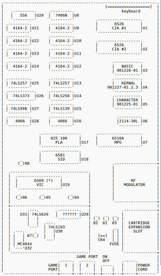
C-64 CHIP LAYOUT

(*) U.S. version of the 6569 [ PAL ] is 6567 [ NTSC ].

HINTS:

1) Over 50% of faulty computers are caused by the external power
supply delivering excessive voltages.

2) Check power supply to see if your unit has a fuse which could be
changed.

3) Check all interconnecting cables.

Replacement Chips (IC’s) can be obtained reasonably from:

Europe --
HRS Electronics Ltd.
Birmingham, England
Tel. # (02)17712525
USA --
(Commodore) National Repair Ctn.
Toll Free 800-248-2983
(800-BIT BYTE)
Asia --
Saysun Electronics Ltd.
Hong Kong
Tel.# (05)767757

Disclaimer: I hereby disclaim any responsibility for the accuracy of
the information on this chart and disclaim all liability for the use
thereof. This chart is supplied as an adjunct to Commodore computer
users. It is intended for assistance in isolating a faulty chip and
is to be used by persons experienced in the repair of computers and
computer related devices.

Printed in Australia – 1986. No path of the Commodore Diagnostician
may be reproduced nor copied for any purpose without the author’s
approval. (c) Copyright.


End of the Project 64 etext of The Commodore Diagnostician.


The Project 64 etext of the Ray’s C-64 Problems Solved. By Ray
Carlson, CARLSEN ELECTRONICS, <rrcc@u.washington.edu>.

C64 Diagnose: Problems I’ve repaired

  • BAS ROM or RAM U3. Pwr up: Title page — Char (garbage) „flash“ but

disappear (blank „page“)

  • PLA U17, KER ROM U4. Pwr up: No title page (blank raster)
  • VIC U19. Garbage screen but loads/runs pgm
  • RAM chip. All garbage screen — no load or run
  • OSC U30. After warmup TV loses horiz sync
  • Pwr supply. No +5V, raster — no title page — no pwr LED
  • C85, 47 [ ?? ]. Pix goes out of horiz hold after 4 hrs+
  • RAM chip. Garbage/flashing chars. Within 1/2 sec of pwr up — Bad

RAM IC (hot)

  • SID chip. Music player: note „hang up“ — „muddy“ sound
  • SID chip. Blown by shorting Audio-In after pwr up — Title page:

goes to garbage

  • U8 buffer. C-64 initializes drive at pwr up but „device not

present“ error

  • U17 PLA. Blank raster
  • U17 PLA. Intermittent cursor on opening screen … it will not move
  • U2 CIA. Semi-random „squares“ on screen at pwr up (no title page)

U2 in 64C. Was 8521RO, I subbed 6526A, works OK (Old IC got hot, too)

  • U17 PLA. „Rainbow“ effect on opening screen characters
  • 1 RAM (not hot!). „Out of memory error“ at pwr up instead of

opening screen

  • SID chip. Erratic mouse pointer, music: notes „hang up“, „muddy“

sound

  • U31 Clock Gen. Horiz way off freq. on monitor
  • U1 CIA. Partial pgm load or screen freeze after run a while, „5“

key repeats if held down, „flashing“ cursor

  • U17 PLA. Pgm crash — back to Basic screen, new chip bad!

End of the Project 64 etext of the Ray’s C-64 Problems Solved.


Various usenet articles about 1541 repair.


Newsgroups: comp.sys.cbm
Subject: Re: 1541 Repair
From: Raymond Carlsen <rrcc@u.washington.edu>
Date: Tue, 4 Jun 1996 17:35:56 -0700

> I have a 1541 that just spins forever when turned on. Both LED’s
> are on. Anyone have any pointers to repair info on this model?

Steve,

    That usually points to a bad DOS ROM chip. It's CBM # 901229-03

(old drives) or -05. A bad 6522 is also a possibility.

Ray Carlsen
CARLSEN ELECTRONICS… A leader in trailing-edge technology.


Newsgroups: comp.sys.cbm
Subject: Re: 1541 Repair
From: Brian Heyboer <bjheyboer@space.honeywell.com>
Date: Wed, 05 Jun 1996 12:08:15 -0400

Steven J Tucker (dh395@cleveland.Freenet.Edu) wrote:

> I have a 1541 that just spins forever when turned on. Both LED’s
> are on. Anyone have any pointers to repair info on this model?

There are several things that can cause this, but the most common is a
bad 901229-05 ROM. The 6502, 6522, RAM, and a couple of the TTL chips
in the reset circuit can also cause it, pretty much in that order of
likelyhood, assuming it just „went bad“ and didn’t fail because of
something you did to it.


Newsgroups: comp.sys.cbm
Date: Wed, 5 Jun 1996 06:54:24 -0700 (PDT)
From: Raymond Carlsen <rrcc@u.washington.edu>
To: Cris Berneburg <74171.2136@compuserve.com>
Subject: Re: 1541 help!

> Well, I’ve done it again. I bought another 1541 drive that doesn’t
> work. The guy told me it was „out of alignment“. Needless to say, that
> was an understatement. So, I need some help trying to fix it.
>
> Here are the symptoms. When I power it on, the red and green LED’s
> both flicker on for about 1/4 of a second, then stay off. The drive
> motor spins constantly when powered on, and will not respond to
> commands. Do you why that is?

The power supply is probably failing. Note that the power indicator is
going out under load. Since the +12 volts runs the motors, try the +5v
line… bet you’ll find a bad bridge rectifier or flaky regulator.

Ray Carlsen
CARLSEN ELECTRONICS… A leader in trailing-edge technology.


From: <judd@merle.acns.nwu.edu>
Date: Wed, 5 Jun 1996 09:27:35 -0500
To: 74171.2136@compuserve.com
Subject: Re: 1541 help!
Newsgroups: comp.sys.cbm
Organization: Northwestern University, Evanston IL

In article <4p3vbp$s7i@dub-news-svc-4.compuserve.com> you write:
>Well, I’ve done it again. I bought another 1541 drive that doesn’t
>work. The guy told me it was „out of alignment“. Needless to say, that
>was an understatement. So, I need some help trying to fix it.
>
>Here are the symptoms. When I power it on, the red and green LED’s
>both flicker on for about 1/4 of a second, then stay off. The drive
>motor spins constantly when powered on, and will not respond to
>commands. Do you why that is?
>
>Here’s what I’ve tried to find out where the problem is. I swapped the
>main processor board with a working drive, and it seemed to power up
>OK. So I put the original, faulty board back in and tried swapping out
>chips. I replaced the 901229-05, 6502, both 6522’s, and the tiny
>EL7407-0284 chip with no posititve effect. No other chips in this
>drive have the chip sockets for easy replacement.
>
>901229-05 6502
> 6522 EL407-0284
> 6522
>
>If you know what the problem is or have some suggestions on what I
>could do to diagnose it, PLEASE! Thanks.
>
>——-
>Cris „PC-Geek“ Berneburg <74171.2136@compuserve.com>
>The Basic Bombardier, Manager of Project 64
>http://ourworld.compuserve.com/homepages/pcgeek/
>PGP public key A1CE4355 available on keyservers
>

The LED flicker tells you immediately that there is a problem with
the power — they aren’t connected to anything else. Most likely
you have a blown rectifier. There are two of them, at the back
of the drive, and they look like this:

	  _____
	 /    |
	/     |
	|     |
	-------
	| | | |

That is, a notched square with four pins coming out of the bottom.
After you power up the drive, at least one of them (the smaller one)
will probably be hotter than blazes.

The fix: go to Radio Shack and buy a new, heftier one for $1 or so,
and solder it in. These are full-wave rectifiers of course.

-Steve

C64 Diagnose: Blank Screen

Ray Carlsen CARLSEN ELECTRONICS… a leader in trailing-edge technology.

Blank screen is the most common symptom, and a failing PLA chip is the most common reason. However, quite a few other failures can cause it as well, such as a bad power supply (check with a known good substitute), bad RAM chip(s), and in general, just about any other chip in there because many chips share multiple data lines. If any one of those lines is loaded down or missing a signal for whatever reason, it can produce that symptom. To narrow it down a bit:

Turn the computer off and back on rapidly about five times. If the screen ever comes up with flashing colors or all one color, the PLA is suspect. Replace it to check. Try a cartridge, such as a game. It essentially „replaces“ some of the chips in the computer when it runs. If a cart works, check the ROMs. The screen may have a normal border even if the CHARacter or BASIC ROMs are bad. A bad Kernal ROM will produce no border.

The internal RF unit outputs a signal that goes to the antenna input of your TV. If the picture is snowy, suspect the RF modulator, assuming the direct video output of the 64 is normal. If the computer is „dead“ but is getting power (red LED on), the modulator will produce a black screen… darker than the blank screen of a failing chip in the computer. A missing 9VAC (power supply problem) is a possiblility. Note that the later C64C will still work without the 9VAC or if the internal fuse opens. However, you will have no sound, the cassette will not work, and the TOD clocks will not work.

See if any of the RAM chips (there are eight of them) get warm or hot… feel each one with the back of your finger after the computer has run for about 5 minutes. Shorted chips will get hotter than the others. Note: bad RAM doesn’t always get hot. See if the computer resets the other components in the system like the drive and/or printer. If so, try a „blind“ disk command and see if the drive responds.. try formatting a disk. If that works, you may have a bad VIC chip (no screen display). Sometimes a bad SID chip will produce a blank screen… pull it out and try the computer. It will run without it, although you will have no sound, and a proportional mouse will not work. The few large chips that normally run hot have a high failure rate: in rough order… the PLA, SID, MPU and the VIC. Static zaps usually take out chips like the CIAs. A shorted CIA can produce a blank screen. Note that you will get the startup screen with the CIA’s removed. You can use that as a diagnostic. The smaller so-called „glue logic“ chips (TTL) run cool and are pretty rugged. Although they rarely fail, I’ve had a few that drove me crazy by making me unsolder a dozen IC’s until I found the bad one. With the above noted exceptions, removing a chip will not allow the computer to produce the startup screen. Removing a chip will in most cases produce a blank screen.

The only practical way to check chips is by substitution. The easiest way to do that is by inserting each suspected chip into a working computer that already has all chips socketed. (You can chase your tail doing it the other way around if you have more than one bad one.) I made a test board for just that purpose. Suspected chip(s) can be tested one at a time and only the bad ones need be replaced. At the very least, you need a source of known good chips for test purposes. Be careful… they are static sensitive. If you don’t want to go to that much trouble to diagnose the problem, you will probably be better off hunting up another C64. Chips are hard to find and expensive. Keep a spare „breadbox“ or two, even if only for parts.

C64 BLANK SCREEN 02-22-99

C64 Diagnose: 1540 und 1541

1540 / 1541 Service Manual

From: Ray Carlsen CET

1541 CHIPS VS SYMPTOMS latest additions or corrections: 2-15-08
This list represents the most common versions of the 1541 in the standard brown case with PC board numbers 1540050 (early ALPSpush-down door mechanism) and the 251830 and 251777 (Newtronics twist door mechanism). Although the very early „long board“ (white case) 1541 is not represented here, major chip functions are of course similar. Thatdrive used more TTL (so-called „glue logic“) chips that were later „integrated“ into a single motor control IC. Although functionally identical, newer drives such as the 1541C and 1541-II integrate more functions into fewer more specialized IC’s, making some repair parts even harder to find. Although most of the chips in the different versions of the standard brown case 1541 are the same, board layout and some chip ID numbers may be different. To eliminate confusion, I will list the two major versions of the drive separately. In another article (fix1541.txt) I will give you some troubleshooting tips. Included is how the drive should behave during normal operation and what is likely to cause a particular fault. Before suspecting any IC chips, don’t overlook more common causes of problems such as a dirty read/write head. Always check the „easy stuff“ first.

1541 CHIPS VS SYMPTOMS PCB# 1540050 (early version) with ALPS drive mechanism (1982)

UA1 74LS14 LOGIC

Partial failure common cause of „FILE NOT FOUND“ error. Total failure: when drive powered up, red LED stays on and spindle motor runs continuously (check also UB4, UC2, UC4, UC5, UC6, UD3, and UD5).

UB1 7406 (M53206P) LOGIC

Partial failure most common causing „SEARCHING FOR“ (also check UC3), or „DEVICE NOT PRESENT“. Total failure: drive may power up normally, but will not reset when the computer is turned on.

UB2 TMM2016AP-10 16K RAM TMM2116AP-15 or MB8128-15

When drive powered up, motor runs continuously and red LED flashes slowly (about 1 flash every 2 seconds).

UB3 325302-01 DOS ROM

When drive powered up, red LED flashes 3 times repeatedly.

UB4 901229-03 or -05 DOS ROM

When drive powered up, red LED stays on and spindle motor runs continuously. DOS ROM is a common failure. Check also UA1, UC2, UC4, UC5, UC6, UD3, and UD5.

UC1 325572-01 MOTOR CONTROLLER

When drive powered up, red LED comes on and goes out, but spindle motor does not turn. When LOAD attempted, spindle does not turn, red LED flickers, screen displays „FILE NOT FOUND“ and red LED flashes.

UC2 6522 VIA (MOTOR CONTROL INTERFACE)

When drive powered up, red LED stays on and spindle motor runs continuously. Check also UA1, UB4, UC4, UC5, UC6, UD3, and UD5.

UC3 6522 VIA (SERIAL INTERFACE)

Drive powers up and resets normally. When LOAD attempted, screen indicates „SEARCHING FOR …“, but no motors run and red LED does not light.

UC4 6502 MPU

When drive powered up, red LED stays on and spindle motor runs continuously. Check also UA1, UB4, UC2, UC5, UC6, UD3, and UD5.

UC5 74LS04 (74LS14) LOGIC

When drive powered up, red LED stays on and spindle motor runs continuously. Check also UA1, UB4, UC2, UC4, UC6, UD3, and UD5.

UC6 74LS00 LOGIC

When drive powered up, red LED stays on and spindle motor runs continuously. Check also UA1, UB4, UC2, UC4, UC5, UD3, and UD5.

UC7 74LS42P LOGIC (DECODER)

When drive powered up, motor runs continuously and red LED flashes slowly (about 1 flash every 2 seconds). Red LED may stay on and/or motor may stop.

UD1 7406 (M53206P) LOGIC

When drive powered up or reset, spindle motor runs momentarily, but red LED doesn’t come on. When LOAD attempted, screen indicates „SEARCHING FOR …“ but red LED does not light, spindle runs continuously, and screen shows „FILE NOT FOUND“ error.

UD2 7417 LOGIC (R/W CONTROL BUFFER)

When drive powered up or reset, red LED comes on and goes out, but spindle motor does not turn. If LOAD is attempted, red LED comes on, stepper moves slightly, spindle doesn’t turn, screen shows „FILE NOT FOUND“ and red LED flashes.

UD3 74LS86 LOGIC

When drive powered up, red LED stays on and spindle motor runs continuously. Check also UA1, UB4, UC2, UC4, UC5, UC6, and UD5.

UD4 9602 (8602) LOGIC (MMV)

Drive powers up and resets normally, but if LOAD is attempted, spindle motor runs with red LED out. Screen displays „SEARCHING FOR …“ and stepper does not move. Check also UE6.

UD5 74LS197 (74177) LOGIC (TIMER)

When drive powered up, red LED stays on and spindle motor runs continuously. Check also UA1, UB4, UC2, UC4, UC5, UC6, and UD3.

UE4 LM311 COMPARITOR (READ LOGIC)

Powers up normally. When LOAD attempted, spindle turns and red LED comes on, but „FILE NOT FOUND“ and red LED flashes. Check also UF3 and UF4.

UE6 74LS193 (7417) LOGIC (BIN COUNTER)

Drive powers up and resets normally, but if LOAD is attempted, spindle motor runs with red LED out. Screen displays „SEARCHING FOR …“ and stepper does not move. Check also UD4.

UF3 NE592N READ PREAMPLIFIER

Powers up normally. When LOAD attempted, spindle runs and red LED comes on, but „FILE NOT FOUND“ and red LED flashes. Check also UE4 and UF4.

UF4 NE592N READ AMPLIFIER

Powers up normally. When LOAD attempted, spindle runs and red LED comes on, but „FILE NOT FOUND“ and red LED flashes. Check also UE4 and UF3.

VR1 UA7812KC (LM340KC-12) +12 VOLT REGULATOR

Drive powers up „normally“, but motors run slowly or not at all. If that happens, drive access will produce a flashing red activity LED and errors „file not found“ or „drive not ready“ on the error channel.

VR2 UA7805KC (LM340KC-5.0) +5 VOLT REGULATOR

Green (power) LED dim, flickers, or does not come on at all, but spindle may run continuously and red LED may be dark.

CR1 2 AMP 200V BRIDGE RECTIFIER (FOR +12V)

Drive appears to power up normally, but motors do not run. Should get warm only if the drive is being accessed (motors running).

CR3 2 AMP 200V BRIDGE RECTIFIER (FOR +5V)

On power up, green and red LED’s are dim or dark and spindle motor runs continuously. May be intermittant and „die“ after warmup. Part runs very hot normally and is a common failure in this model.

1541 CHIPS VS SYMPTOMS PCB# 251830 or 251777 with Newtronics drive mechanism (1984)

UA1 74LS14 LOGIC

Partial failure common cause of „FILE NOT FOUND“ error. Total failure: when drive powered up, red LED stays on and spindle motor runs continuously (check also UB4, UC2, UC4, UC6, UC7, UD3, and UD5).

UB1 7406 (M53206P or 7707) LOGIC

Partial failure common cause of „SEARCHING FOR“ (check also UC3) and „DEVICE NOT PRESENT“ errors. Total failure: drive powers up OK, but does not respond to computer… no reset or disk access.

UB2 TMM2016AP-10 16K RAM TMM2116AP-15 or MB8128-15

When drive powered up, spindle motor runs continuously and red LED flashes about once every two seconds.

UB3 325302-01 DOS ROM

When drive powered up, red LED flashes 3 times repeatedly.

UB4 901229-03 or -05 DOS ROM

When drive powered up, red LED stays on and spindle motor runs continuously. DOS ROM is a common failure. Check also UA1, UC2, UC4, UC6, UC7, UD3, and UD5.

UC1 325572-01 MOTOR CONTROLLER

When drive powered up or reset, red LED comes on and goes out, but spindle motor does not turn. When LOAD attempted, spindle does not turn, red LED flickers, screen displays „FILE NOT FOUND“ and red LED flashes.

UC2 6522 VIA (MOTOR CONTROL INTERFACE)

When drive powered up, red LED stays on and spindle motor runs continuously. Check also UA1, UB4, UC4, UC6, UC7, UD3, and UD5.

UC3 6522 VIA (SERIAL INTERFACE)

Drive powers up and resets normally. When LOAD is attempted, screen indicates „SEARCHING FOR …“, but no motors run and red LED does not light.

UC4 6502 MPU

When drive powered up, red LED stays on and spindle motor runs continuously. Check also UA1, UB4, UC2, UC6, UC7, UD3, and UD5.

UC6 74LS04 (7713) LOGIC

When drive powered up, red LED stays on and spindle motor runs continuously. Check also UA1, UB4, UC2, UC4, UC7, UD3, and UD5.

UC7 74LS00 LOGIC

When drive powered up, red LED stays on and spindle motor runs continuously. Check also UA1, UB4, UC2, UC4, UC6, UD3, and UD5.

UC8 74LS42 LOGIC

When drive powered up, spindle motor runs continuously. Red LED may stay on, or flash three times and go out.

UD1 7406 (M53206P) LOGIC

When powered up, spindle motor runs momentarily, but red LED doesn’t come on. When LOAD attempted, screen indicates „SEARCHING FOR …“ but red LED does not light and spindle runs continuously.

UD2 7407 (7417) LOGIC (R/W CONTROL BUFFER)

When drive is powered up or reset from computer, red LED comes on and goes out, but spindle motor does not turn. When LOAD is attempted, stepper moves slightly, spindle doesn’t turn, and error message on screen is „FILE NOT FOUND“ with flashing red LED.

UD3 74LS86 LOGIC

When drive powered up, red LED stays on and spindle motor runs continuously. Check also UA1, UB4, UC2, UC4, UC6, UC7, and UD5.

UD4 9602 (74123) LOGIC (MMV)

Drive powers up and resets normally, but when LOAD is attempted, screen indicates „SEARCHING FOR …“ red LED does not light and spindle runs continuously. Check also UE6.

UD5 74LS197 (74177) LOGIC (TIMER)

When drive powered up, red LED stays on and spindle motor runs continuously. Check also UA1, UB4, UC2, UC4, UC6, UC7, and UD3.

UE4 LM311 COMPARITOR (READ)

Drive powers up and resets normally. Spindle motor runs, stepper moves slightly, but „FILE NOT FOUND“ error, and red LED flashes. Check also UF3 and UF4.

UE6 74LS193 (7417 or 7407) LOGIC (COUNTER)

Drive powers up and resets normally, but when LOAD is attempted, screen indicates „SEARCHING FOR …“ red LED does not light and spindle runs continuously. Check also UD4.

UF3 NE592N (LM592) READ PREAMP

Drive powers up and resets normally. Spindle motor runs, stepper moves slightly, but „FILE NOT FOUND“ error and red LED flashes. Check also UF4 and UE4.

UF4 NE592N (LM592) READ AMPLIFIER

Drive powers up and resets normally. Spindle motor runs, stepper moves slightly, but „FILE NOT FOUND“ error and red LED flashes. Check also UF3 and UE4.

VR1 UA7812KC (LM340KC-12) +12 VOLT REGULATOR

When powered up, green power LED comes on and red LED comes on and goes out normally, but motors do not run (or move slowly). Drive access will produce a flashing red activity LED and error messages „file not found“ or „drive not ready“ on the error channel.

VR2 UA7805KC (LM340KC-5.0) +5 VOLT REGULATOR

Green (power) LED dim, flickers, or does not come on at all. Drive appears dead, but spindle motor runs continuously.

CR1 2 AMP 200V BRIDGE RECTIFIER (FOR +5V)

Drive appears dead, but spindle motor runs continuously with both green and red LEDs dim or dark. May be intermittant and fail after warmup. This part normally runs hot and is a common failure item.

CR3 2 AMP 200V BRIDGE RECTIFIER (FOR +12V)

Drive appears to power up normally, but motors do not run. Should get warm only if drive is accessed (motors running).

Notes: UC2, UC3, UB4, and regulators VR1 and VR2 run warm normally and bridge rectifiers CR1 and CR3 run very hot if drive is being accessed. Otherwise, only CR3 will get hot.

Newtronics drives (twist type door latch) normally run a bit noiser (stepper chatter) than earlier ALPS (push down door) types.

Ray Carlsen CET CARLSEN ELECTRONICS… a leader in trailing-edge technology. Questions and comments are welcome, especially if you spot a mistake here. Thanks!