Alle Beiträge von vzekcwebmaster

C64 Ersatz-Ein-/Ausschalter

Im Forum hat Gerrit als Lösung mit einen 0,25€ Schalter von Pollin vorgestellt (Link)

Nachdem die Ersatzschalter bei Retro-Donald ausverkauft sind und anscheinend auch nicht wieder reinkommen habe ich mich mal umgesehen was als Ersatz benutzbar wäre. Muss ja nicht perfekt sein sondern von aussen stilecht aussehen und funktionieren.

Letzte Woche habe ich bei Pollin die Nummer 420 632 für einen unschlagbaren Preis (25 Cent!) gefunden und gleich ein paar bestellt. Sieht auf dem Bild nicht besonders passend aus, aber wie man auf den angehängten Bildern sieht ist die Wippe nur aufgeklipst, die gleiche Art der Befestigung der Wippe wie bei den Originalschaltern des C64, mit einem sehr kleinen Schraubenzieher hatte ich kein Problem sie zu entfernen (siehe Bild 2) und die Wippe eines defekten C64-Schalter aufzuklipsen. Das löst schonmal das erste Problem und man könnte ihn direkt in einem C16 oder Plus/4 verwenden. Für die Verwendung in einem C64 ist etwas Bearbeitung der Anschlüsse nötig wie man auf dem dritten Bild sieht. Hierbei mit Gefühl arbeiten und sich etwas Zeit lassen. Drei davon kann man direkt passend biegen, der vierte braucht eine Verlängerung, ich habe mir einen Draht des defekten Schalters geliehen. Die zwei übrigen Anschlüsse werden im C64 nicht verwendet, also habe ich sie einfach entfernt. Ergebnis: C64 funktioniert wieder und ein sattes Schaltgefühl.

Natürlich ist das ein Hack, aber ich finde besser so als kein Schalter… .Müsste genauso mit den Schaltern einer 1541-II, eines C128 und einer 1581 funktionieren.

Schalter:

Wippenhalterung:

Der eingebaute Schalter:

C64 Diagnose: The Commodore Diagnostician by Ian Perry

The Project 64 etext for Commodore diagnostics, converted by The
Basic Bombardier. This etext was created by concatenating several
documents into one. Please see the header of the particular document
for original sources.

The Commodore Diagnostician, by Ian Perry.
Ray’s C-64 Problems Solved, by Ray Carlson.
Various usenet articles about 1541 repair.

C-DIAG10.TXT, June 1996, etext #45.


The Project 64 etext of The Commodore Diagnostician. Tables were
converted to list format.


THE COMMODORE DIAGNOSTICIAN

A symptomatic chart for diagnosing faulty IC
components on Commodore Computers and peripherals

By: IAN PERRY, MA

   PO Box 48
   Kyneton
   Victoria 3444
   Australia

COMMODORE C-64 Reference Aid #4

SYMPTOMS & POSSIBLE SOLUTION

  • Cursor jumps back to home position. 6510
  • Abnormal colours appear in the letters. PLA
  • Different characters are displayed and cursor is locked when turned

on and off. 6510, 6567

  • System does not reset and the ‚RESTORE‘ key does not work. 6510,

PLA, ROM 227

  • Cursor disappears after the system warms up. 6526
  • SYNTAX ERROR displayed after system warms up. ROM 226
  • The system resets when it warms up and long programs do not load.

6510, ROM 226

  • Keyboard does not operate correctly when the system warms up.6526,

ROM 226

  • Cassette motor keeps running. 6510
  • The cursor disappears when the cassette is plugged in. 6510
  • Cassette runs extremely slow. The program seems to load but will

not run. 6510

  • Blank screen on power up. 6510, 6567, PLA, 8701 [, RAM ]
  • No cursor displayed. Intermittent blank screen. Intermittent

graphics. 6510

  • Powers up with ‚PRESS PLAY ON TAPE‘ message and the display blanks.

6510

  • On power up the cursor locks up. 6510
  • When ‚RETURN‘ is pressed after a run command, the cursor goes back

to home position. ROM 226

  • Poke command does not work. ROM 226
  • Joystick does not operate correctly. 6526
  • No character lettering is displayed on the screen. 6526, 6567,

PLA, ROM 225

  • Graphic characters instead of letters displayed. 6526, 6567
  • Power up message appears but no cursor. 6526, ROM 226
  • DEVICE NOT PRESENT ERROR is displayed when disk is used. 6510,

6526

  • Disk drives continue to search when trying to load. 6526
  • Incorrect screen colours or no colour at all. 6567, PLA
  • Keyboard does not function. 6526
  • Cassette recorder problem. 6510, 6526
  • Flashing colour or blocks. PLA
  • Game Cartridge does not function. PLA, ROM 227
  • Unit dead (30-40% possibility PLA). PLA
  • User port does not function (eg. modem). 6526
  • No sound. 6581 [, Bad RF Modulator ]
  • Missing notes. 6581
  • Game paddles do not function. 6526, 6581
  • White band scrolls down the screen (60 HZ HUM). Check power supply

and VR2 regulator.

  • Wavy screen after the system warms up. Check external power supply

and 6567 chip.

  • Black band scrolls through screen when system warms up. Check

external power supply and VR2 regulator.

  • Out of memory error on power up. Check Rams 4146 U1-U12,

U21-U24. [ May be Hot! ]

  • Powers up with graphic display and blinking cursor. Check U14.
  • Powers up with all the characters displayed as blocks. Check U26.
  • Unit completely dead. Possible power supply failure.
  • After a few minutes, characters are all over the screen, then the

unit locks up. Possible power supply problem.

Note-PLA chip is an 82S100, ROM chips are 901226-01 (Basic),
901227-01 (Kernal), 901225-01 (Character)

COMMODORE 1541/1571 FLOPPY DRIVE

SYMPTOMS & POSSIBLE SOLUTION

  • Error LED stays on all the time. 6501, ROM 32530201, ROM 90122905
  • Drive motor runs continuously and red LED stays on. 6522 [, LED

Flashes: UC7 ]

  • Drive motor runs continuously and red LED stays off. 6502, ROM

90122905

  • After the drive warms up the motor runs continuously. 6522
  • Does not load when hot or LED flashed 3 times. ROM 90122905, LM311
  • Searches with LED flashing continuously. ROM 90122905
  • Searching with no red LED. ROM 3253021
  • Drive fails to read. LM311, 592, 9602
  • Fails to format disk. 6522, ROM 32557201
  • Stepper Motor does not step forward. 6502, 6522
  • Will not save when the drive heats up. 6502
  • Lights stay on, motor runs continuously. Is Power cord plugged into

wall outlet correctly? Is Power cord plugged into disk drive
correctly? Check line fuse and power switch. Check +5/12 volt
lines.

  • No LED’s on power up. Check all RAM and ROM locations.
  • Error LED flashes on power up.
  • Drive motor runs continuously with no red or green LED’S. Check

VR2. Check Power Transformer. [ Hint: No Reg. +5V ]

  • Loads programs with red LED flashing. Check drive speed. Check

stepper motor.

  • Loading is intermittent. Check ROM’s and drive alignment.
  • Message of ‚FILE NOT FOUND‘ is displayed. Clean drive head

w/alcohol. Check 0 stop adjustment. Check alignment. [ Check for
sticky slide rails. 1571: Check head lifter release mech. ]

  • Drive speed will not stabilize. Check DC motor. [ Check belt (old

drives)]

  • Locks-up when loading. Check serial port components. Check

901229-05.

  • Fails the performance test and displays a 21 read error. Check

test diskette. Check Drive Motor.

  • Fails the performance test and displays a 27 read error. Check

stop adjust.

  • Passes performance test to track 18 then displays 21 read errors.

Check read/write head.

  • Passes the performance test but will not load certain programs.

Check stepper motor.

  • Flashing light on and off during loading. An alignment problem or

bad diskette.

C-64 CHIP LAYOUT

(*) U.S. version of the 6569 [ PAL ] is 6567 [ NTSC ].

HINTS:

1) Over 50% of faulty computers are caused by the external power
supply delivering excessive voltages.

2) Check power supply to see if your unit has a fuse which could be
changed.

3) Check all interconnecting cables.

Replacement Chips (IC’s) can be obtained reasonably from:

Europe --
HRS Electronics Ltd.
Birmingham, England
Tel. # (02)17712525
USA --
(Commodore) National Repair Ctn.
Toll Free 800-248-2983
(800-BIT BYTE)
Asia --
Saysun Electronics Ltd.
Hong Kong
Tel.# (05)767757

Disclaimer: I hereby disclaim any responsibility for the accuracy of
the information on this chart and disclaim all liability for the use
thereof. This chart is supplied as an adjunct to Commodore computer
users. It is intended for assistance in isolating a faulty chip and
is to be used by persons experienced in the repair of computers and
computer related devices.

Printed in Australia – 1986. No path of the Commodore Diagnostician
may be reproduced nor copied for any purpose without the author’s
approval. (c) Copyright.


End of the Project 64 etext of The Commodore Diagnostician.


The Project 64 etext of the Ray’s C-64 Problems Solved. By Ray
Carlson, CARLSEN ELECTRONICS, <rrcc@u.washington.edu>.

C64 Diagnose: Einleitung und Dokumente

Diagnose-Unterlagen

Hier liegen zwei Dokumente für den Service eines Commodore C64:

Welcome to Project 64!

The goal of Project 64 is to preserve Commodore 64 related documents
in electronic text format that might otherwise cease to exist with the
rapid advancement of computer technology and declining interest in 8-
bit computers on the part of the general population. If you would like
to help by converting C64 related hardcopy documents to electronic
texts please contact the manager of Project 64, Cris Berneburg, at
<74171.2136@compuserve.com>.

Extensive efforts were made to preserve the contents of the original
document. However, certain portions, such as diagrams, program
listings, and indexes may have been either altered or sacrificed due
to the limitations of plain vanilla text. Diagrams may have been
eliminated where ASCII-art was not feasible. Program listings may be
missing display codes where substitutions were not possible. Tables
of contents and indexes may have been changed from page number
references to section number references. Please accept our apologies
for these limitations, alterations, and possible omissions.

Document names are limited to the 8.3 file convention of DOS. The
first characters of the file name are an abbreviation of the original
document name. The version number of the etext follows next. After
that a letter may appear to indicate the particular source of the
document. Finally, the document is given a .TXT extension.

The author(s) of the original document and members of Project 64 make
no representations about the accuracy or suitability of this material
for any purpose. This etext is provided „as-is“. Please refer to the
warantee of the original document, if any, that may included in this
etext. No other warantees, express or implied, are made to you as to
the etext or any medium it may be on. Neither the author(s) nor the
members of Project 64 will assume liability for damages either from
the direct or indirect use of this etext or from the distribution of
or modification to this etext.

C64 Diagnose: Problems I’ve repaired

  • BAS ROM or RAM U3. Pwr up: Title page — Char (garbage) „flash“ but

disappear (blank „page“)

  • PLA U17, KER ROM U4. Pwr up: No title page (blank raster)
  • VIC U19. Garbage screen but loads/runs pgm
  • RAM chip. All garbage screen — no load or run
  • OSC U30. After warmup TV loses horiz sync
  • Pwr supply. No +5V, raster — no title page — no pwr LED
  • C85, 47 [ ?? ]. Pix goes out of horiz hold after 4 hrs+
  • RAM chip. Garbage/flashing chars. Within 1/2 sec of pwr up — Bad

RAM IC (hot)

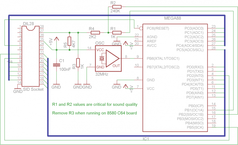
  • SID chip. Music player: note „hang up“ — „muddy“ sound
  • SID chip. Blown by shorting Audio-In after pwr up — Title page:

goes to garbage

  • U8 buffer. C-64 initializes drive at pwr up but „device not

present“ error

  • U17 PLA. Blank raster
  • U17 PLA. Intermittent cursor on opening screen … it will not move
  • U2 CIA. Semi-random „squares“ on screen at pwr up (no title page)

U2 in 64C. Was 8521RO, I subbed 6526A, works OK (Old IC got hot, too)

  • U17 PLA. „Rainbow“ effect on opening screen characters
  • 1 RAM (not hot!). „Out of memory error“ at pwr up instead of

opening screen

  • SID chip. Erratic mouse pointer, music: notes „hang up“, „muddy“

sound

  • U31 Clock Gen. Horiz way off freq. on monitor
  • U1 CIA. Partial pgm load or screen freeze after run a while, „5“

key repeats if held down, „flashing“ cursor

  • U17 PLA. Pgm crash — back to Basic screen, new chip bad!

End of the Project 64 etext of the Ray’s C-64 Problems Solved.


Various usenet articles about 1541 repair.


Newsgroups: comp.sys.cbm
Subject: Re: 1541 Repair
From: Raymond Carlsen <rrcc@u.washington.edu>
Date: Tue, 4 Jun 1996 17:35:56 -0700

> I have a 1541 that just spins forever when turned on. Both LED’s
> are on. Anyone have any pointers to repair info on this model?

Steve,

    That usually points to a bad DOS ROM chip. It's CBM # 901229-03

(old drives) or -05. A bad 6522 is also a possibility.

Ray Carlsen
CARLSEN ELECTRONICS… A leader in trailing-edge technology.


Newsgroups: comp.sys.cbm
Subject: Re: 1541 Repair
From: Brian Heyboer <bjheyboer@space.honeywell.com>
Date: Wed, 05 Jun 1996 12:08:15 -0400

Steven J Tucker (dh395@cleveland.Freenet.Edu) wrote:

> I have a 1541 that just spins forever when turned on. Both LED’s
> are on. Anyone have any pointers to repair info on this model?

There are several things that can cause this, but the most common is a
bad 901229-05 ROM. The 6502, 6522, RAM, and a couple of the TTL chips
in the reset circuit can also cause it, pretty much in that order of
likelyhood, assuming it just „went bad“ and didn’t fail because of
something you did to it.


Newsgroups: comp.sys.cbm
Date: Wed, 5 Jun 1996 06:54:24 -0700 (PDT)
From: Raymond Carlsen <rrcc@u.washington.edu>
To: Cris Berneburg <74171.2136@compuserve.com>
Subject: Re: 1541 help!

> Well, I’ve done it again. I bought another 1541 drive that doesn’t
> work. The guy told me it was „out of alignment“. Needless to say, that
> was an understatement. So, I need some help trying to fix it.
>
> Here are the symptoms. When I power it on, the red and green LED’s
> both flicker on for about 1/4 of a second, then stay off. The drive
> motor spins constantly when powered on, and will not respond to
> commands. Do you why that is?

The power supply is probably failing. Note that the power indicator is
going out under load. Since the +12 volts runs the motors, try the +5v
line… bet you’ll find a bad bridge rectifier or flaky regulator.

Ray Carlsen
CARLSEN ELECTRONICS… A leader in trailing-edge technology.


From: <judd@merle.acns.nwu.edu>
Date: Wed, 5 Jun 1996 09:27:35 -0500
To: 74171.2136@compuserve.com
Subject: Re: 1541 help!
Newsgroups: comp.sys.cbm
Organization: Northwestern University, Evanston IL

In article <4p3vbp$s7i@dub-news-svc-4.compuserve.com> you write:
>Well, I’ve done it again. I bought another 1541 drive that doesn’t
>work. The guy told me it was „out of alignment“. Needless to say, that
>was an understatement. So, I need some help trying to fix it.
>
>Here are the symptoms. When I power it on, the red and green LED’s
>both flicker on for about 1/4 of a second, then stay off. The drive
>motor spins constantly when powered on, and will not respond to
>commands. Do you why that is?
>
>Here’s what I’ve tried to find out where the problem is. I swapped the
>main processor board with a working drive, and it seemed to power up
>OK. So I put the original, faulty board back in and tried swapping out
>chips. I replaced the 901229-05, 6502, both 6522’s, and the tiny
>EL7407-0284 chip with no posititve effect. No other chips in this
>drive have the chip sockets for easy replacement.
>
>901229-05 6502
> 6522 EL407-0284
> 6522
>
>If you know what the problem is or have some suggestions on what I
>could do to diagnose it, PLEASE! Thanks.
>
>——-
>Cris „PC-Geek“ Berneburg <74171.2136@compuserve.com>
>The Basic Bombardier, Manager of Project 64
>http://ourworld.compuserve.com/homepages/pcgeek/
>PGP public key A1CE4355 available on keyservers
>

The LED flicker tells you immediately that there is a problem with
the power — they aren’t connected to anything else. Most likely
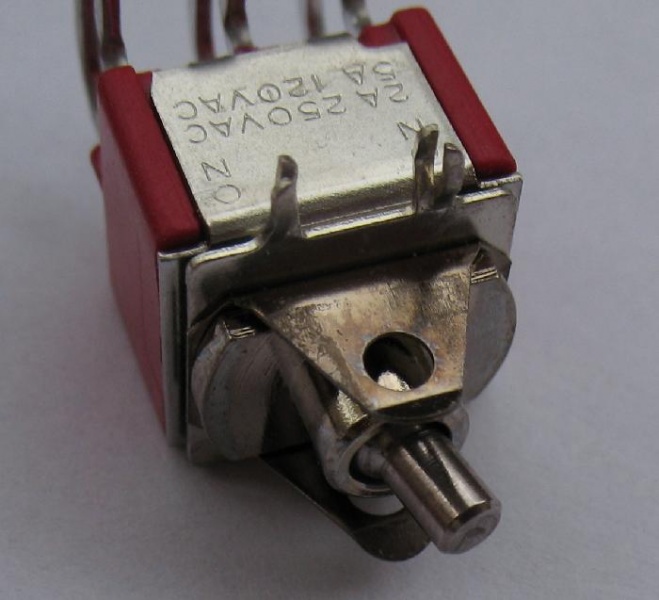
you have a blown rectifier. There are two of them, at the back
of the drive, and they look like this:

	  _____
	 /    |
	/     |
	|     |
	-------
	| | | |

That is, a notched square with four pins coming out of the bottom.
After you power up the drive, at least one of them (the smaller one)
will probably be hotter than blazes.

The fix: go to Radio Shack and buy a new, heftier one for $1 or so,
and solder it in. These are full-wave rectifiers of course.

-Steve

C64 Ersatz SID

Eine 100% vollwärtigen Ersatz des Soundchips im C64 gibt es z.Z nicht. Aber selbst die orig. Chips klingen alle etwas unterschiedlich 😉

Es gibt aber einen Ersatz auf ATmega88 Basis.

Stückliste: Part Value Device Package Library Sheet

  1. C1 100nF C2.5/2 C2.5-2 capacitor-wima 1
  2. DIL28 SID Socket DIL28 DIL28-6 ic-package 1
  3. IC1 MEGA88-PA MEGA88-PA DIL28-3 atmel 1
  4. OSC 32MHz QG5860 DIL14S crystal 1
  5. R1 1K R-EU_0204/7 0204/7 rcl 1
  6. R2 240K R-EU_0204/7 0204/7 rcl 1
  7. R3 1K R-EU_0204/7 0204/7 rcl 1
  8. R4 2K2 R-EU_0204/7 0204/7 rcl 1
  9. R5 4K7 R-EU_0204/7 0204/7 rcl 1

ZIP Archive mit Eagle-Dateien, Firmware HEX und Batchdatei zum Flashen mit Fuses:
SwinSID88.zip

Schaltplan:

Board:

Bild der Platine im C64 eingebaut:

C 64 Ersatz PLA

Die PLA im C64 ist ein Logikbaustein. Die Logikgleichungen wurden entschlüsselt und heute gibt es sowohl professionelle Nachbauten auf CPLD Basis (Retro-Donald Shop) als auch eine Simulation auf Basis eines 27C512 Eproms. Das hier verfügbare Layout ist zwar 2-seitig und könnte ohne Probleme auch 1-seitig geroutet werden, den meisten PCB Herstellern ist das aber inzwischen egal und sparen kann man dabei fast nichts mehr.

Eprom-Bin & Eagle Layout Dateien: Ersatz-PLA.zip

VEB / Robotron Linksammlung

Hier sammeln wir interessante Links zu den Homecomputern aus der DDR.

  1. DDR Vergleichstypen (Mailbox Datenbestand aus Leipzig)

Commodore Linksammlung

Hier sammeln wir interessante Links und Ressourcen zu Commodore Systemen.

  1. PET und CBM
  2. Commodore C64
  3. Commodore (Alle Modelle)

Linkliste Bezugsquellen

Hier sammeln wir Links zu Händlern und Portalen für klassische Computer, Software und Zubehör.

CBM Manuals von Compirudi

Die Manuals sind auf dem Mirror auf https://cbmmanuals1.classic-computing.org/index.shtml verfügbar.